Author: iwi

Gentoo web2py daemon

Gentoo RC init script for web2py framework

Save as “/etc/init.d/web2py”

#!/sbin/runscript
# Gentoo web2py init script

WORK_PATH="/home/web2py"
WORK_FILE="web2py.py"

PYTHON="/usr/bin/python2.6"
PIDFILE="/var/run/web2py.pid"

PASSWORD="<recycle>"
SRV_ADDR="0.0.0.0"
SRV_PORT="8000"
SRV_CRT=""
SRV_KEY=""

depend(){
  need net
}

start() {
  ebegin "Starting web2py"
  start-stop-daemon --start --quiet --background --chdir "$WORK_PATH" \
                    --pidfile $PIDFILE --exec "$PYTHON" \
                    -- "$WORK_PATH/$WORK_FILE" \
                    --nogui --password="$PASSWORD" \
                    --pid_filename="$PIDFILE" \
                    --ip=$SRV_ADDR --port=$SRV_PORT \
                    --ssl_certificate="$SRV_CRT" --ssl_private_key="$SRV_KEY"
  eend $?
}

stop() {
  ebegin "Stopping web2py"
  start-stop-daemon --stop --pidfile $PIDFILE
  eend $?
}

To make a file executable:
chmode +x /etc/init.d/web2py
Add to default runlevel:
rc-update add web2py default
Start daemon:
rc-config start web2py

Remove Windows 7 password

This is the most easiest way to remove password of Windows system. Works on all Windows [NT/XP/Vista/Seven] – [32/64] versions.

DANGER!
If used on users that have EFS encrypted files, and the system is XP or newer, all encrypted files for that user will be UNREADABLE! If you don’t know if you have encrypted files or not, you most likely don’t have them. (except maybe on corporate systems)

It’s floppy based Linux distribution, partially derived from floppyfw.
Boot [CD/Floppy] downloads and instructions can be found at:
http://pogostick.net/~pnh/ntpasswd/

This floppy image is in the SYSRESCUECD, also instructions to make Boot USB Pen Drive: http://www.sysresccd.org/Sysresccd-manual-en_How_to_install_SystemRescueCd_on_an_USB-stick

Python GUI calc

Python GUI experiment. Simple calculator application made with Tk.
It’s a first choice because it’s integrated into Python, simple to use and powerful enough for most cases. It’s also cross platform like an interpreter.
However, there are many other libraries for GUI:
http://wiki.python.org/moin/GuiProgramming

#!/usr/bin/python

# Python GUI calculator 
# (C) 2011 - netquote.it
# Original code by Emanuele Chiabrera
# Enhanced by Toropov Ivan 

from Tkinter import *

# button text list
cmdlst = ['7', '8', '9', '+', '%',
          '4', '5', '6', '-', '**',
          '1', '2', '3', '*', '//',
          '.', '0', 'CL', '/', '=']

class MyButton(Button):
    
    backref = None
    
    def Click(self):
        # back reference
        self.backref.BtnCmd(self["text"])


class CalcApp:

    def __init__(self, master):
        frame = Frame(master)
        
        self.textbox = Entry(width=30, takefocus=1)
        self.textbox.pack(side=TOP)
        self.textbox.focus_force()

        self.buttons = []
        for n, c in enumerate(cmdlst):
            self.buttons.append(MyButton(frame, text=c, width=5))
            self.buttons[n]["command"] = self.buttons[n].Click
            self.buttons[n].backref = self
            self.buttons[n].grid(row=n/5, column=n%5)

        frame.pack()

    def BtnCmd(self, cmd):
        if cmd == '=':
            try:
                res = eval(self.textbox.get())
            except:
                res = "Error!"
            self.textbox.delete(0, END)
            self.textbox.insert(0, str(res))
        elif cmd == 'CL':
            self.textbox.delete(0, END)
        else:
            self.textbox.insert(END, cmd)

root = Tk()
root.title("EWCalc")

calcapp = CalcApp(root)
root.mainloop()

What comes out:

Voltage Drop Protection

DC motor drive circuit with automatic load regulation. Main concept is to cut off power from DC Motor and sustain the voltage in the circuit. Also detect low-battery state.

Components:
#1 – Dual Op-Amp CA158 (Like LM358)
#1 – Trimmer 4.7 kΩ (voltage limit regulator)
#1 – NPN-MOSFET IRF530 (14A, 100V)
#1 – Capacitor C 0,1 µF
#1 – Capacitor C 0,33 µF
#1 – Led (Green – Bat ok)
#1 – Led (Red – Bat low)
#2 – Resistor R 220 Ω
#3 – Resistor R 15 kΩ
#1 – Brushed DC-Motor Permax 400 (6V)

Fonera 2.0n hardware

Model Name

Fonera SDK is originally based on Ralink SDK, also derived from OpenWRT project.

Build instructions can be found on this pages:
http://wiki.fon.com/wiki/Fonera_2.0n
https://www.netquote.it/nqmain/2011/02/fonera-2-0n-hardware/
http://trac.fonosfera.org/fon-ng/wiki/build

Download and build sources:
svn co http://svn.fonosfera.org/fon-ng/tags/2.3.6.1/ fon-sdk
cd fon-sdk/
chmod +x install.sh
./install.sh
cd openwrt
make menuconfig


FON2303
Dimensions
30 mm x 157 mm x 127 mm (excluding antenna)
Power
12VDC, 1A (It seems to work with 6VDC)
Ports
#1 – USB 2.0/1.1
#1 – Ethernet WAN 10/100Mbps
#4 – Ethernet LAN 10/100Mbps
Antennas
#2 – 3dBi Dipole Fixed Antennas
CPU
SoC Ralink RT3052F 320/384 MHz MIPS24KEc
RAM
64 MB – (32 MB cpu internal + 2×16 MB external PSC A3V56S40ETP-G6)
Flash
8 MB – MX29LV640DBTC-90G

External links:
Product briefing
RT3052F CPU Ref.
Ralink ApSoC SDK 3301
SDK User’s manual
MX29LV640DBTC-90G

Fonera SDK is originally based on Ralink SDK, also derived from OpenWRT project.

Build instructions can be found on this pages:
http://wiki.fon.com/wiki/Fonera_2.0n
https://www.netquote.it/nqmain/2011/02/fonera-2-0n-hardware/
http://trac.fonosfera.org/fon-ng/wiki/build

Download and build sources:
svn co http://svn.fonosfera.org/fon-ng/tags/2.3.6.1/ fon-sdk
cd fon-sdk/
chmod +x install.sh
./install.sh
cd openwrt
make menuconfig

Dead after a few difficult years 🙁


Boost & RCF on Mac OSX with Xcode

Litle HowTo prepare Boost and RCF on Mac!
My work environment is Mac OS X Snow Leopard 10.6.6 and Xcode 3.2.5
Boost version is 1.45.0 and RCF version is 1.3

What is Boost and RCF?
Boost is a powerful and portable C++ library.
RCF is a Remote Call Framework something like RPC.

The two libraries written in C++ seems to be Cross Platform and Cross Compiler also 64 bit.
From RCF documentation only one thing must be done.
Use of the typedef’s in “boost/cstdint.hpp” for portability.

The first step is to download and compile boost.
The official site is http://www.boost.org/

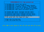
Extract downloaded file to your working directory, start terminal and navigate to the root of the extracted boost directory then execute “bootstrap.sh”
It’s build a bjam command-line tool that drives the Boost Build system.

cd ~/Documents/boost_1_45_0/
./bootstrap.sh --with-libraries=all

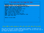
Run bjam and wait, wait a lot!

./bjam --layout=tagged variant=debug -j 2 architecture=combined-x86-power stage

————(OPTIONS)————
--toolset=darwin
Apple’s version of the GCC toolchain with support for Darwin and MacOS X features such as frameworks.
--build-type=complete
Build all supported variants of the libraries.
--layout=tagged
Names of boost binaries include the encoded build properties such as variant and threading.
--with-<libraryname>
Build specified library.
--show-libraries
Displays the list of Boost libraries.
--clean
Remove targets instead of building.
-j N
Run up to N commands in parallel. Only for multiprocessor compilation.
————(PROPERTIES)————
address-model=32,64,32_64
Explicitly request either 32-bit or 64-bit code generation.
runtime-link=shared,static
Linking to the C++ standard library and compiler runtime support libraries.
link=shared,static
Determines if bjam creates shared or static libraries.
threading=single,multi
Cause the produced binaries to be thread-safe.
variant=debug,release,profile,debug-python
Choosing a specific build variant by adding release or debug.
architecture=x86,ia64,power,combined,combined-x86-power

Now boost library is compiled and ready. Next step is RCF framework.
The Official site is http://deltavsoft.com/
Download and extract RCF-1.3 to your working directory.

Create a new command-line project with Xcode.
Don’t forget to select “C++ stdc++” in Type box!

Go to “Project” menu and select “Edit project Settings” then select “Build” tag. Search for “Header Search Paths” settings and append RCF and Boost include path in the list. Search for Preprocessor Macro and add “RCF_USE_BOOST_ASIO”. Set also “Library Search Path” to “boost_1_45_0/stage/lib”.

Finally in the main window go to “Source” select and right-click, select “Add”, then “Existing Files”, navigate to “RCF-1.3/src/RCF”, find and add “RCF.cpp” file. Also go to “Targets” -> “Link Binary With Libraries” and add “libboost_system.a” and others “.a” files from the “boost_1_45_0/stage/lib” directory.

Open main.cpp and insert test code.

#include <iostream>
#include <rcf /Idl.hpp>
#include </rcf><rcf /RcfServer.hpp>
#include </rcf><rcf /TcpEndpoint.hpp>

RCF_BEGIN(I_Echo, "I_Echo")
RCF_METHOD_R1(std::string, echo, std::string)
RCF_END(I_Echo)

class Echo
{
public:
    std::string echo(const std::string &s)
    {
        return s;
    }
};

int main (int argc, char * const argv[])
{
	Echo echo;
	RCF::RcfServer server( RCF::TcpEndpoint("127.0.0.1", 50001));
	server.bind<I_Echo>(echo);
	server.start();
	std::cout < < "Server running..." << std::endl;

	RcfClient<I_Echo> client( RCF::TcpEndpoint("127.0.0.1", 50001));

	std::string dts;
	std::cin >> dts;

	std::string ecs = client.echo(dts);

	std::cout << "Echo: " << ecs << std::endl;

    return 0;
}

External links:
Boost.Build is a high-level build system http://www.highscore.de/cpp/boostbuild/
RCF User Guide http://deltavsoft.com/w/RcfUserGuide/1.3/index.html
Linking Custom Static Libraries from your iPhone Xcode Projects http://wiki.remobjects.com/wiki/Linking_Custom_Static_Libraries_from_your_iPhone_Xcode_Projects
The Boost C++ Libraries BoostBook Documentation Subset http://www.boost.org/doc/libs/1_45_0/doc/html/index.html
Compiling Boost for the iPhone http://iphone.galloway.me.uk/2009/11/compiling-boost-for-the-iphone/

Fonera 2.0n USB boot script

Some time ago I wrote script for Hacking Fonera Access Point. This script move root file system to USB device and permit any kind of installation and easily revert any changes to original state without stress for internal flash drive. In fact it’s stress USB device but it’s better than damage the internal flash!

How it works:
First time the script copy entire Fonera root file system to USB device, next time everything except kernel is loaded from external USB. If no valid USB drive/partition is detected it’s automatically load internal root file system after about 20s.

Preparing USB drive:
Create on USB device one or more partition with ext2 or ext3 file system. Finally add an empty file named “usbrootfsready” on the root of partition.

Preparing Fonera:
We need to gain access to Fonera shell and create file named “/sbin/usbrootfs” with this contents.

#!/bin/sh
# Fonera2.0n usbrootfs
# Copyright (C) 2009 iwi \at\ hotmail \it\
# exec > /home/usbroot.log 2>&1

USBROOT="/dev/sda1"
USBMNTP="/mnt"
USBFLAG="/usbrootfsready"

/sbin/insmod ext2
/sbin/insmod jbd
/sbin/insmod ext3
/sbin/insmod dwc_otg

for CNTR in $(seq 1 1 10)
do
    sleep 2s
    if [ -b "$USBROOT" ]; then 
        mount -o rw "$USBROOT" "$USBMNTP" && {
            if [ -f "$USBMNTP$USBFLAG" ]; then
                # Copy to new root
                rm "$USBMNTP$USBFLAG"
                cd /rom
                tar -c * | tar -x -C $USBMNTP
                cd /jffs
                tar -c * | tar -x -C $USBMNTP
                cd $USBMNTP
                rm `find | grep META_`
                rmdir jffs
                #rm var
                #mkdir var
                mkdir /usr/lib/opkg
                cd /
            fi
            if [ -f "$USBMNTP/sbin/init" ]; then
                # remount usb as rootfs
                mount -o move /proc $USBMNTP/proc && {
                    pivot_root $USBMNTP $USBMNTP/rom && {
                        mount -o move /rom/dev /dev
                        mount -o move /rom/sys /sys
                        mount -o move /rom/tmp /tmp
                        break
                    }
                    mount -o move $USBMNTP/proc /proc
                }
            fi
            umount "$USBROOT"
        }
        break
    fi
done

Now delete or rename “sbin/init” and create new init file.

#!/bin/sh
# Fonera2.0n init override
# Copyright (C) 2009 Toropov Ivan

/sbin/usbrootfs

exec /bin/busybox init

Don’t forget to mark this files as executables.

chmod +x /sbin/init
chmod +x /sbin/usbrootfs

It’s all. Reboot and enjoy hacking!

MaxSonar sensor and pySerial

LV-MaxSonar-EZ0 sensor by MaxBotix.

Interfacing with computer serial port and Python via pySerial module.

Download Python and pySerial.

The wiring is so trivial. Start from data sheet we need 4 pins: GND, VCC, TX, RX.
Sensor operating voltage is from 2.5V to 5.5V and the current is about 2mA, then we can get power from serial port DTR or RTS pins. Look at this explanation. ATTENTION! RS-232 specification says that tension can be 25V. You can simply BURN the sonar, computer, house and more… Don’t do anything if you don’t know what are you doing.

In my case I am using USB to RS-232 converter. Output voltage is 5V so I don’t need additional circuitry, just simple pin to pin wiring.

And now little coding…


# Import pySerial module
from serial import *

# Open serial port and setup
ser = Serial("COM10", baudrate=9600, bytesize=8, parity='N', stopbits=1, timeout=1)

# Power up MaxSonar via DTR pin
ser.setDTR(True)

# Infinite loop
while (True):

    # Read serial data
    data = ser.read(5)

    # Check data length 
    if len(data) == 5:

        # Check data packet
        if data[0] == "R" and data[1:4].isdigit():

            # Convert to cm and print 
            print int(data[1:4]) * 2.54, "cm"

    # Request next measurement        
    ser.write(0)

# Close 
ser.close()

Many thanks to Antonio Bugnone for soldering.

Curve fitting with Python

First we need a NumPy and MatPlotLib modules.

Look at curve fitting explanation from wiki.

Second degree polynomial equation would help us: y=ax^2 + bx + c
This will exactly fit a simple curve to three points.
Using more points we get a nearest possible curve.


# Import modules
from numpy import *
from matplotlib.pyplot import *

# Input data (change it)
# X and Y points must have same length
x = [1,  2,  4,   6]
y = [10, 3,  7,  -6]

# (a, b, c) coefficients computation
coefficients = polyfit(x, y, 2)

# With coefficients we make a polynomial object
poly = poly1d(coefficients)

# Create point series
xs = arange(min(x)-1, max(x)+1, 0.05)

# Calculate resultant series
ys = poly(xs)

# Finally draw everything
plot(xs, ys)
plot(x, y, 'o')

# X and Y axis label
ylabel('y')
xlabel('x')

# And show
show()

Using 3 points:
x = [1, 2, 4]
y = [10, 3, 7]

Using 4 points:
x = [1, 2, 4, 6]
y = [10, 3, 7, -6]